Product Security and Risk Mitigation for USB Power Delivery (PD) Based Systems
Introduction to USB Power Delivery
8/29/2019
For many good reasons, USB Power Delivery (PD) adoption continues to grow throughout the electronics industry. Perhaps the largest draw of USB PD is the use of the USB Type-C connector, which consolidates high speed data (via USB 3.0-3.2) and power (via USB PD) into a single connection. This is attractive from both engineering and industrial design viewpoints.
USB PD, as envisioned by the USB Implementers Forum (USB-IF), permits a high degree of compatibility between generic USB PD sources and consumer devices. That is, one USB PD source can power a wide range of devices, each potentially from a different manufacturer.
However, the quality of USB PD sources varies greatly between manufacturers, especially from a user safety perspective. A USB PD source which is fully compliant with the USB PD protocol does not imply that it is safe, or appropriate for every application. Precautions should be taken to account for unintentional connection of unqualified power supplies.
Problem Statement
To ensure system robustness and user safety, mission critical systems often require adherence to a wide range of industry and/or government standards. Using an unqualified power supply with a mission critical system can be detrimental to a system’s performance, and may cause the system to fall out of compliance with those industry or government standards.
Traditionally, unintentional connection can be managed with mechanical restrictions such as unique connector types, pinouts, ID resistors, and/or keyed overmolds. While GlobTek could provide these solutions to achieve this goal, they would conflict with the USB standards.
This issue is a major concern for medical system designers who need to consider the risk associated with powering their medical device from a non-medically-approved power source.
GlobTek’s USB PD offerings are fully approved for medical and ITE applications, but other manufacturers’ offerings may not be. Medical devices must use power supplies designed for, and certified to, IEC60601. Similarly, power supplies for ITE must be certified to IEC60950/62368. A non-certified power supply can expose patients and/or operators to risks associated with low dielectric withstand voltage and/or high leakage current.
This paper explores two methods, standard in GlobTek’s PD products, for mitigating risk associated with unintended connection of an unauthorized USB PD power source to a host system. Please contact GlobTek for a solution tailored to your needs.
Method 1 (Non-Standard Voltages)
A USB PD source typically has the ability to supply a range of output voltages, depending on the requirements of the host system. The USB PD 3.0 specification defines a set of four “normative” voltages: 5V, 9V, 15V, and 20V. Most systems using USB PD will be designed to operate from one or more of these voltages, for maximum power source flexibility.
However, a USB PD system can also be designed around non-standard voltages, that is, voltages not part of the normative set, as defined above. For GlobTek PD power sources, 5V is always applied to the USB connector by default. To “negotiate” to a higher voltage/power level, the host system must request a new power data object (PDO) from the source. Figure 1 shows a simplified USB PD negotiation sequence for a typical USB PD system.
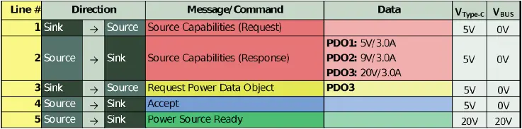
Figure 1: Power negotiation for a typical USB PD system
Both the power source and power sink require USB PD compliant controllers to facilitate this interaction. The sink’s PD controller stores a list of acceptable PDOs in non-volatile memory. When the sink receives the source’s capabilities, the sink PD controller compares its list to the PDO list provided by the source. Typically, the sink PD controller selects the highest power match between the two lists, as shown in Figure 2.
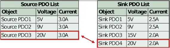
Figure 2: Typical sink controller logic for selection of highest power PDO
If the sink PD controller contains non-standard PDOs, then it will only properly negotiate to those PDOs if the source also contains matching, non-standard PDOs. If there is no match (i.e. an unauthorized source is attached), then the source defaults to PDO1, 5V. See Figure 3 below.
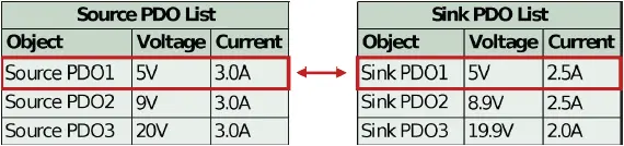
Figure 3: Sink controller logic when no higher power matches are found (default to PDO1)
To completely reject an unauthorized power supply, system designers may choose to disconnect VIN (VType-C) from VBUS when the default 5V PDO is selected. Many off-the-shelf PD controllers contain this functionality. Furthermore, the system designer may also consider disconnecting the system’s ground from the local ground used by the USB PD sink controller, to provide further isolation from the power source.
GlobTek’s GTM96605-GEN2 contains a 15.1V power profile for this use. Other non-standard voltages are available upon request.
Pros:
- Easy to implement using an off-the-shelf USB PD sink controller
- Prevents the vast majority of consumer- grade USB PD power sources from working
Cons:
- It is possible that an unauthorized source may contain a matching, non-standard PDO
- If standard PDOs are replaced with non-standard PDOs, then the power adapter may not be fully compatible with ordinary USB PD devices (tablets, phones, etc.)
Method 2 (Vendor Defined Messages)
Communication between two USB PD devices is facilitated over the CC line. At a minimum, a USB PD controller must support the baseline feature-set which allows power profile negotiation. However, the USB PD specification also allows for devices to send and receive messages that are outside the scope of “normal” USB PD communication. These messages are called Vendor Defined Messages (VDMs).
In the case of “authenticating” a power source, VDMs can be used to request additional product information from the source, to check whether it is genuine or not. There are several possibilities for implementing a solution based on VDMs. A suggested method is shown below, in Figure 4.
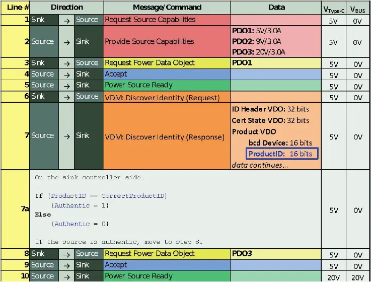
Figure 4: Proposed method for implementing Vendor Defined Messages for source authentication
Implementing a solution based on VDMs requires logic typically not available in off-the-shelf USB PD controllers. In this case, the USB PD interface can be implemented on a microcontroller. Some manufacturers (STMicroelectronics, Cypress, and others) offer microcontrollers with integrated USB PD functionality alongside a qualified firmware stack, to streamline development. The standard firmware can be modified to implement custom logic, as shown above.
GlobTek’s GTM96605-GEN2 will respond to a VDM Discover Identity request with 0x4754 in the Product ID field. (This value corresponds to ‘GT’ in ASCII.)
Note: The VDM approach does not make use of secure/encrypted keys.
Pros:
- Permits use of any voltage, including normative voltages like 5V, 9V, 15V, and 20V, allowing simultaneous compatibility with ordinary USB PD devices
- If used in conjunction with non-standard voltages, provides an extra level of risk mitigation
- Potentially more difficult to work around for counterfeiters, increasing revenue from replacement parts
Cons:
- More difficult to implement, requires a microcontroller and custom firmware
Final Words
It is important to note that implementing the aforementioned methods does not guarantee a safe medical (or other) system. A system designer should be careful to assess the risk associated with using USB PD on his/her product. It is difficult to completely safeguard a product from a power source which has failed in a catastrophic way. System designers should also consider how power from the USB Type-C connector is applied and/or removed from internal system circuits. Making/breaking both positive and negative connections (like a DPST switch) may provide better isolation. All possibilities should be considered in the product’s risk management plan.