PSU Isolation and Identity
David Love, GlobTek GTUS, Northvale Design Center
Explanation of Class I and Class II Input
- Class I:
- One level/means of insulation to protect the end-user of the product (customer system) from the AC mains voltage. An additional means of protection must be provided by using a safety earth ground connection. The safety earth connection (attached to the PSU output), needs to be able to handle 25 amps of current for 5 to 10 seconds of time, and be less than 100 milli-ohms resistance at the end of this period, per the 60601-1 M.E. standard. This classification was originally intended for products in metal housings, and the heavy earth ground wire would be from the mains earth connection to the metal housing. However, with the evolution of the plastic encased power adapter, many companies chose to use a transformer design with primitive single means of insulation, and an earthed negative output. However, present day power adapter SMPS technology will always utilize a double insulated transformer, since at present time double insulating the xfmr does not cause a large increase in size, due to development of (TIW) triple insulated wire technology.
- Class II:
- Two levels/means of insulation, or one means of reinforced (double strength) insulation, to protect the end-user of the product (customer system) from the AC mains voltage. This classification must be used if a 2 conductor AC input, with no earth connection.
- Class II with FE (Functional Earth):
- This category of isolation is most easily understood as a 3 conductor input connection (with earth), but it is not a Class I configuration. The earth wire becomes defined as Functional, which is opposite of Safety earth. The FE wire may be used for a few different purposes, as follows:
- Reduce output AC leakage current (compared to a Class II unit)
- Reduce output DC leakage current (compared to a Class I unit)
- Reduce EFT (Electrical Fast Transient) coupling path from earth wire at input to the customer system ground, to prevent system glitches.
- Reduce CE (conducted emissions)
- Provide output isolation, but allow a 3 conductor input, as generally preferred by most North American hospitals.
Configuration Issues and Solutions
As discussed above, there are a few different configuration issues, which may be clarified from the descriptions below:
OUTPUT LEAKAGE CURRENT:
Medical systems (inclusive of customer equipment), have limits for patient leakage current and touch current. Although the PSU does not have a direct patient applied part, it is often the case, that the customer system will not require (or provide) an extra layer of insulation between the patient and the M.E., in order to either increase reliability, improve accuracy of transducers/sensors or decrease system cost. By having a minimum leakage current at the output of the power supply to earth, the system analysis and measurement of patient leakage current is benefitted.
TOUCH CURRENT:
M.E. as well as typical consumer and industrial equipment, is required to meet touch current requirements, for the various safety standards. When the plastic housing is directly touched, by the human hand simulator at the safety lab, a very small current typically flows, only about 1 to 2 uA. However if the exposed metal of the output connector is contacted, a higher level of touch current may flow. For medical equipment, this current level is limited to 100uA.
AC LEAKAGE CURRENT:
For a medical product, touch current limits are 100uA AC, and also 100uA DC. The majority of the AC leakage current, is the result of the 50Hz or 60Hz mains power at the PSU input. However, there is also a small amount of the AC leakage current which is the result of high frequency switching action of the power conversion process. Note, the human body has a higher sensitivity to electrical shock with frequencies below 1KHz. Therefore the safety specifications typically use a single pole low pass filter, with a cutoff frequency of 1KHz. Since most high frequency switching occurs at roughly 100KHz, we rarely see issues with high frequency switching currents, exception is the extremely simple EMI filters used in the 6W and 10W power products. Passing the output AC leakage current back to the earth terminal on a 3 wire input PSU helps to reduce this potential issue.
DC LEAKAGE CURRENT:
When the power supply output is tied directly to earth as is the case with a Class I input configuration, M.E. system leakage current compliance issues may develop in certain cases. The root cause may be understood, by the voltage drop in the output cord, which if it exceeds 100mV, can cause the customer apparatus to fail the 100uA DC leakage current limit at any exposed metal surfaces which attach to the negative rail. The reason that such a low DC voltage may cause failure of the leakage current limit, is that the defined probe impedance for the human body is 1K ohms resistance. If 1K ohms resistance is placed across 100mV of DC voltage, then 100uA of current will flow. Isolating the DC output prevents this potential system compliance issue.
EFT (Electrical fast Transient), 61000-4-4 IMMUNITY TEST:
The EFT immunity test, is applied on 3 ports individually, and in combination. The 3 ports are the AC Line, AC Neutral and Earth. The EFT energy pulses are applied by an electrical transient generator, thru 3 separate LISNs (Line Impedance Stabilization Networks). When the energy pulse train (AKA burst of pulses) is applied to the earth wire at the input, the high frequency noise energy travels directly to the customer M.E. without any filtering, if the isolation configuration is Class I. If a customer M.E. system performance is suffering during this test, addition of high frequency impedance in series with earth wire will help significantly. Typically an impedance of 1K ohms at the problem frequencies (100KHz to 100MHz) will be beneficial to prevent the M.E. system from glitching.
CONDUCTED EMISSIONS:
When a Class I output configuration is requested, usually the CE is increased by 4 to 6dB in comparison to the levels of a Class II configuration. By electrically isolating the earth wire from the output negative with roughly 1K ohms impedance, the worst case CE level will usually be reduced.
OUTPUT ISOLATION FOR M.E.:
There are 3 basic isolation categories of M.E. as follows:
B – Body, this does not require earth isolation of the M.E.
BF- Body Floating, this type of M.E. requires electrical isolation from earth
CF- Cardiac Floating, this type of M.E. also requires electrical isolation from earth
Although a M.E. system could use an extra level of electrical insulation between the PSU and the patient, thus allowing use of a Class I PSU, it is often more beneficial to provide the earth isolation in the power supply itself. Additionally, the BF and CF isolation types of M.E. are considered more critical, and thus a medical PSU product which can meet this requirement, may simplify overall system M.E. compliance.
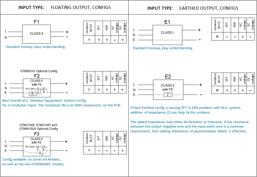
ISOLATION DIAGRAMS and OUTPUT CONNECTOR DIAGRAMS
The 5 isolation diagrams F1, F2, F3, E1 and E2 are available as GlobTek options, however F2 and F3 have limited scope as defined on their diagrams. Each of the diagrams has a small table of advantages and disadvantages of the specific isolation type. When a customer problem arises these tables may help identify a path forward to problem remediation.
OUTPUT CONNECTOR HOOK-UP CONFIGURATIONS
(Use suffix letters: Blank/Null, A, B, or C)
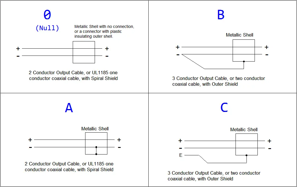
OUTPUT CONNECTOR OPTION CONSIDERATIONS:
A 3 conductor cable with configuration C, often presents difficulty during hipot. Hipot breakdown may occur somewhere between 100Vac and 1000Vac depending on the type of connector selected and the internal spacing in the connector. During the application of an input to output hipot of 4000Vac, often a large voltage, such as 2000Vac will develop between the output wires and the earth, but the connector can not handle the voltage. Therefore, it becomes necessary to first hipot the power supply with the output connector shell attached the negative output at 4000Vac, and then use a second hipot operation at a lower DC voltage of 100Vac to 500Vac. Additionally, the requirements for spacing from earth to output is violated if the PSU is expected to provide BF or CF isolation, when using configuration C.
When a metal shell exists, and a 2 conductor output cable I used, it is pragmatic to discuss with the customer if they must have an electrical connection to the shell. It is less manual labor to not attach to the shell connection in most cases. The GT production department would most likely prefer to make it without the extra wiring inside the connector shell.
Note, when referring to a combined configuration of isolation plus connector hookup, if the zero/Null connector config is needed, then a simple 2 character code identifier is expected. If A, B, or C output hookup is needed, then a 3 character code identifier would be expected, for a clean definition. Simply add the connector hookup suffix to the isolation configuration identifier code.
EXAMPLES of CONFIGURATION SELECTION METHOD:
- Ex 1, Code E1 and then E2
- The customer has requested a Class I model, but after starting testing discovers the system is failing EFT. Changing to the E2 configuration can fix the issue, and the output will still be hard-earthed.
- Ex 2, Code F2A
- Customer requires a 3 conductor input, with a floating earth connection. The customer needs a special output connector with a metal shell, which is required to be hooked up to the output negative.
- Ex 3, Code F1B
- Customer requires a Class II input (typically a C8 connector, but may also be a C18 connector), customer using a special expensive connector, and requests a 3 conductor output cord (2 center conductors plus a shield)